
Update : I build a simple app to control Devices on this webserver. (visit Here)
Introduction:
In this post, we will see how we can build a web server using the ESP8266 NodeMcu device. This web server will be used to control the status of all the devices connected to the Nodemcu. Also, it can be accessed and controlled from any device’s web browser present in the same network.
What is a Web server and how it works?
Web server is a place that stores, processes and delivers web pages to Web clients. The web client is nothing but a web browser on our laptops and smartphones. The communication between client and server takes place using Hypertext Transfer Protocol (HTTP) thorugh a web browser.
CODE:
The entire code for this project is available at the following github repository:https://github.com/htgdokania/Arduino_Webserver
Structure/Work Flow:
- Step1: Download and set up the Arduino IDE along with Esp8266 requirements.
- Step2: Make the LED connections to the Nodemcu module.
- Step3: Write the code and Upload it from the Arduino IDE.
- Step4: Open Web browser to control the device
Step1: Download and set up the Arduino IDE along with Esp8266 requirements.
- First, go to this link and download Arduino IDE and install it.
- Next, we need to install the ESP8266 add-on for the Arduino IDE. For that, go to File > Preferences.
- Enter http://arduino.esp8266.com/stable/package_esp8266com_index.json into the “Additional Board Manager URLs”.

- Then, click the “OK” button.
- Next,Go to Tools > Board > Boards Manager.
- search “esp8266” .Select and install “esp8266 by ESP8266 Community”.(It will take some time)

- Finally, Go to Tools > Board and choose your ESP8266 board.(ESP-12E)

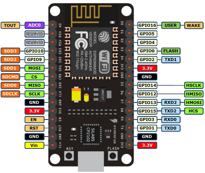
Step2: Make the connections to the Nodemcu module.
Connect Each LED through a 1kohm resistor. to a GPIO pin of NodeMCU. Here we have connected to GPIO4 (D1) and GPIO5
(D2).

Step3: Write the code and Upload it from the Arduino IDE.
We can create a web server using two methods:
Soft Access Point Mode(AP)
In AP mode ESP8266 creates a new WiFi network and sets SSID (Name of the network) and IP address to it. With this IP address, it can deliver web pages to all connected devices under its own network
Station Mode (STA).
The ESP8266 that connects to an existing WiFi network (one created by your wireless router) is called Station (STA)
Let’s Have a look at AP mode first,where we do not need any external wifi network.
- First, we include the ESP8266WiFi library.
// Load Wi-Fi library
#include <ESP8266WiFi.h>
#include <ESP8266WebServer.h>
- Set ssid and password of your wifi network
/* Put any  SSID & Password */
const char* ssid = "Arduino Webserver";  // Enter SSID here
const char* password = "12345678";  //Enter Password here (min 8 characters)
- Next ,set IP address details as follows , you can even change the local IP as per your choice
/* Set  IP Address details */
IPAddress local_ip(192,168,1,1);
IPAddress gateway(192,168,1,1);
IPAddress subnet(255,255,255,0);
- Then, you set your web server to port 80. If you want you can set any other port like “8081”
// Set webserver port number to 80
ESP8266WebServer server(80);
- Define LED pin numbers along with their initial status variables(boolean type )
uint8_t LED1pin = D1;
bool LED1 = LOW;

uint8_t LED2pin = D2;
bool LED2 = LOW;
- Next, write the void setup part:
- Set LED pins as output kind
- Define different server URLs, along with the function they will trigger.
- Finally, start the server and print the local IP.
void setup() {
  Serial.begin(115200);
  pinMode(LED1pin, OUTPUT);
  pinMode(LED2pin, OUTPUT);

  WiFi.softAP(ssid, password);
  WiFi.softAPConfig(local_ip, gateway, subnet);
  delay(100);

  server.on("/",OnConnect);
  server.on("/led1on",led1on);
  server.on("/led1off",led1off);
  server.on("/led2on",led2on);
  server.on("/led2off",led2off);
  server.onNotFound(NotFound);

  server.begin();
  Serial.println("HTTP server started");
  Serial.println(WiFi.localIP());
}
- Inside Void loop() function all we need to do is
- To handle HTTP requests, we need to call the
handleClient()method on the server object. - Update LED status as per HTTP request.
- To handle HTTP requests, we need to call the
void loop() {
  server.handleClient();
  if(LED1)
    digitalWrite(LED1pin, HIGH);
  else
    digitalWrite(LED1pin, LOW);

  if(LED2)
    digitalWrite(LED2pin, HIGH);
  else
    digitalWrite(LED2pin, LOW);
}
- Next, Lets us define the functions that will be triggered when the different URLs defined above will be envoked .
- In order to respond to the HTTP request, we use the server.send method defined in update_status function. Here we also attach a simple HTML page containing buttons to toggle the device status.
Note:sendHTML() function is defined below
void update_status(){
  server.send(200, "text/html", SendHTML(LED1,LED2));  // we send HTML page alng with updated LED status.
}
- Next we define onconnect function which we attach to root( /) URL.
void OnConnect() {
  LED1 = LOW;
  LED2 = LOW;
  update_status();
}
- Next we define the functions to change LED status between ON & OFF
void led1on() {
  LED1 = HIGH;
  update_status();
}

void led1off() {
  LED1 = LOW;
  update_status();
}

void led2on() {
  LED2 = HIGH;
  update_status();
}

void led2off() {
  LED2 = LOW;
  update_status();
}
Finally we attach a function which is used for all the invalid URLs
void NotFound(){
  server.send(404, "text/plain", "Not found");
}
Up to This part, our main server code is done and can be uploaded and run to see the LEDs turn on and off when the specific URL is typed in the address bar.
Now for better controls/Visual GUI interface, we also add a HTML page with buttons and device current status info for easy toggle operations.
- Lets define the SendHTML function:
- The first text we send is <!DOCTYPE> declaration that indicates that we’re sending HTML code.
- the <meta> viewport element makes the web page responsive in any web browser
- Next, we give a Title to our web page “Device control”
- Next, we have some CSS to style the buttons and the web page appearance. Also set color, font, margin, etc
String SendHTML(uint8_t led1stat,uint8_t led2stat){
  String ptr = "<!DOCTYPE html> <html>\n";
  ptr +="<head><meta name=\"viewport\" content=\"width=device-width, initial-scale=1.0, user-scalable=no\">\n";
  ptr +="<title>Device Control</title>\n";
  ptr +="<style>html { font-family: Arial; display: inline-block; margin: 0px auto; text-align: center;}\n";
  ptr +="body{margin-top: 50px;} h1 {color: #343444;margin: 50px auto 30px;} h3 {color: #434444;margin-bottom: 50px;}\n";
Next , we define the button Types ON and OFF .Also set its color, shape,and other features.
  ptr +=".button {display: block;width: 100px;background-color: #1abc9c;border:none;color: white;padding: 13px 30px;text-decoration: none;font-size: 25px;margin: 0px auto 35px;cursor: pointer;border-radius: 50%;}\n";
  ptr +=".button-on {background-color: #ff9900;}\n";
  ptr +=".button-on:active {background-color: #996633;}\n";
  ptr +=".button-off {background-color: #003399;}\n";
  ptr +=".button-off:active {background-color: #003366;}\n";
Next set the font size,color,margin and finally close the style and head and start the body of our HTML page
  ptr +="p {font-size: 14px;color: #888;margin-bottom: 10px;}\n";
  ptr +="</style>\n";
  ptr +="</head>\n";
  ptr +="<body>\n";
First we add the Heading to the web page inside the body.
ptr +="<h1>ESP8266 based Arduino Web Server</h1>\n";
Next display Buttons for the two different devices based on the current state of the device using if else condition:
 if(led1stat)
      ptr +="<p>Device1 Status: ON</p><a class=\"button button-off\" href=\"/led1off\">OFF</a>\n";
  else
      ptr +="<p>Device2 Status: OFF</p><a class=\"button button-on\" href=\"/led1on\">ON</a>\n";

  if(led2stat)
      ptr +="<p>LED2 Status: ON</p><a class=\"button button-off\" href=\"/led2off\">OFF</a>\n";
  else
      ptr +="<p>LED2 Status: OFF</p><a class=\"button button-on\" href=\"/led2on\">ON</a>\n";
Finally end the body and html and return the ptr string,which is send as a response to the http request.
  ptr +="</body>\n";
  ptr +="</html>\n";
  return ptr;
}
Step4: Open Web browser to control the device
Simply connect to the wifi network created by the nodemcu device from any laptop or phone.

Next, open a webbrowser and type in the Ip address you set.You can also see the same from serial monitor . I have used “192.168.1.1“
By default Both the devices will be in OFF state . Simply toggle the switch to see your LEDs turn on and off instantly.


Note: Try changing the url manually instead and see how your devices still changes state.
Now,Let’s Have a look at STA Mode ,where we connect to an existing wifi network.
- First replace the ssid and password with your wifi network’s Credential in line 5,6 of the above code.
/* Put your SSID & Password */
const char* ssid = "Replace_with_your_wifi_SSID";  // Enter SSID here
const char* password = "Replace_With_Your_Wifi_Password";  //Enter Password here
In this mode, the only difference is that we are not setting the soft Access Point using WiFi.softAP(SSID, password);
Instead, we are joining the existing network using Wifi.begin()function. So We Replace line 23,24,25 which were previously.
  WiFi.softAP(ssid, password);
  WiFi.softAPConfig(local_ip, gateway, subnet);
  delay(100);
- We Replace the above line with the following new lines.
  //Connect to your  wi-fi network
  WiFi.begin(ssid, password);
  delay(100);

  //check wi-fi is connected to wi-fi network
  while (WiFi.status() != WL_CONNECTED) {
  delay(1000);
  Serial.print(".");
  }
- Upload the code to the NodeMCU module.
- Once uploaded,open Serial monitor and set the baud rate to 115200
- Next, press the reset button on the NodeMCU.

- You will get the local IP address assigned printed on the screen.
Open this IP address in any device’s web browser and rest all is just similar to what we got in the previous section (AP mode).
Make sure the client device is connected to the same wifi network.
That’s All we need to build our very own Web server using Arduino.


